| Item/Model |
Unit |
| Table Diameter |
mm |
| Diameter of Table Central Hole |
mm |
| Inner Diameter of Mandrel Sleeve |
mm |
| Diameter of Center Through Hole |
mm |
| Table Height (Horizontal) |
mm |
| Table T-slot Width |
mm |
| Guide Block Width |
mm |
| Axis |
- |
| Min. Increment |
deg. |
| Indexing Precision |
sec. |
| Repeatability |
sec. |
Clamping System (Hydraulic)
|
kg/cm2 |
| Clamping Torque |
kg-m |
| Servo Motor Model |
FANUC |
Taper/Straight shaft |
| MITSUBISHI |
Taper shaft |
| Speed Reduction Ratio |
- |
| Max. Rotation Rate of Table (Calculate with Fanuc α Motor) |
r.p.m |
| Allowable Inertia Load Capacity (Horizontal) |
kg.cm.sec2 |
| Allowable Workpiece Load |
0º Horizontal |
kg |
0º~90º Tilt |
kg |
| Allowable Load(with Rotary Table Clamping) |
F |
kgf |
FxL |
kgf.m |
FxL |
kgf.m |
Strength of worm gears (Rotary axis) |
kg.m |
| Net Weight (servo motor excluded) |
kg |

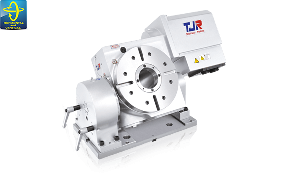
-255-series-model.png)
-255-3See.jpg)